Swimlane Diagram: Symbols, Examples, and How to Create One
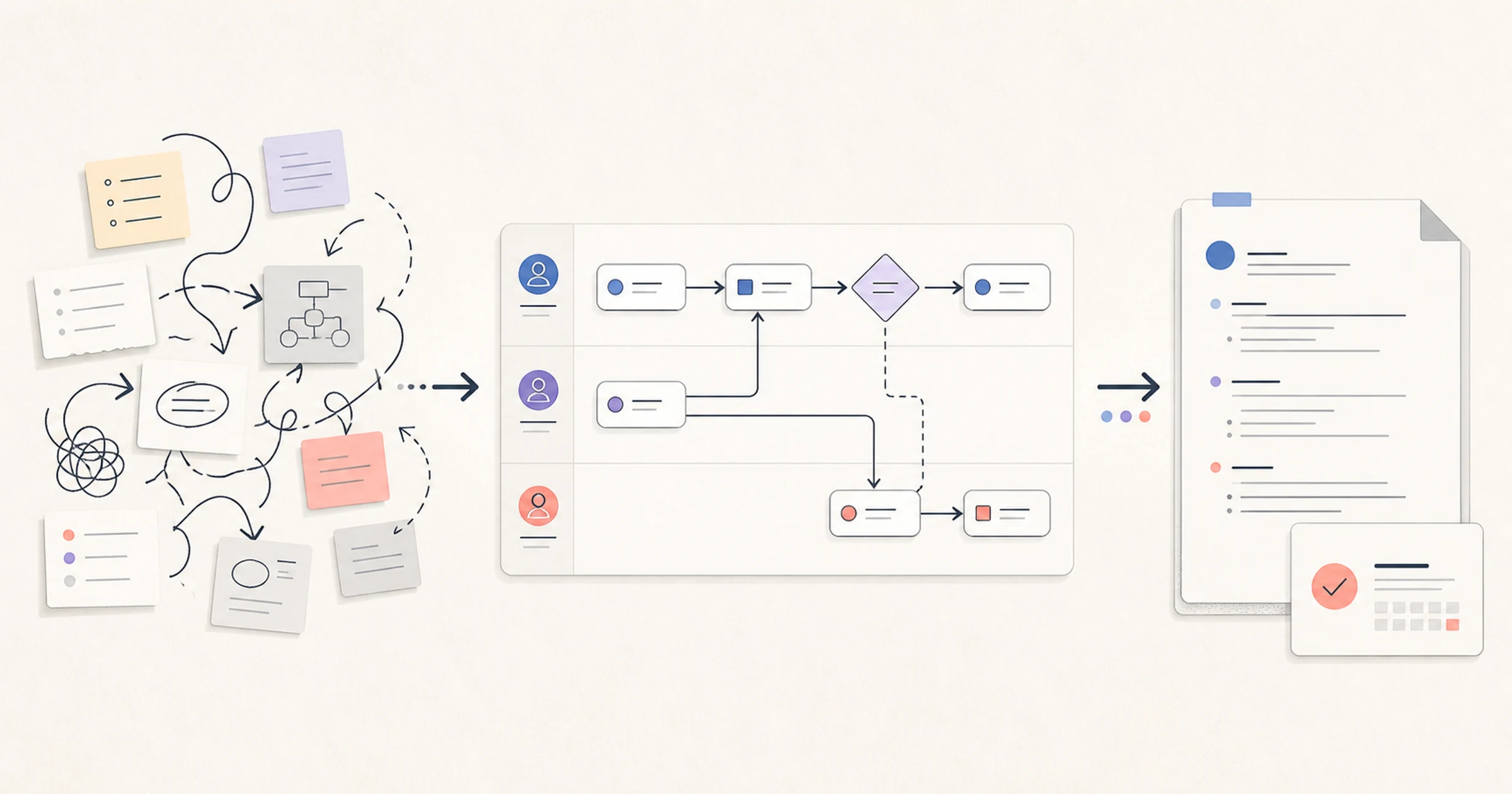
A swimlane diagram is a process flow divided into parallel lanes, with each lane representing a participant, team, role, system, or other area of responsibility. Activities sit in the lane responsible for performing them, while connectors show how work and information move within and across those responsibilities.
The format is useful because an ordinary sequence can hide ownership. “Verify the order, create the account, and schedule kickoff” looks simple until the team asks who verifies the order, what evidence must arrive, where the account is created, and what happens when a required field is missing. A swimlane diagram makes those handoffs discussable.
Definition: A swimlane diagram is a flowchart organized by responsibility. It shows the order of work and who or what performs each activity, making handoffs, decisions, delays, and unclear ownership easier to inspect.
This guide uses flexible everyday swimlanes for practical process analysis and clearly marks where formal Business Process Model and Notation (BPMN) rules begin. Its customer-onboarding example is fictional, not an AFFiNE process or customer case study.
When should you use a swimlane diagram?
Use a swimlane diagram when the process crosses a boundary that matters. Typical uses include:
- a customer journey that moves among Sales, Success, Finance, and Product;
- an approval flow shared by employees, managers, HR, and payroll;
- an incident or support escalation crossing people and systems;
- any current-state process where teams disagree about who acts next.
The diagram can expose duplicated checks, long handoff chains, missing decisions, undefined inputs, and rework. It cannot measure duration or prove causation without supporting evidence.
For broader scoping and evidence guidance, start with business process mapping. Use the swimlane format when responsibility and cross-functional movement are central to the question.
Swimlane diagram template: fields to capture
Use a visual diagram for the flow and keep this text table beside it as an accessible source of truth. One row represents one activity or decision.
| Step ID | Lane or owner | Trigger/input | Activity or decision | Output | Next step | System/evidence | Exception | Validation status |
|---|---|---|---|---|---|---|---|---|
| S01 | Responsible participant | What makes this step ready? | One verb-led action or explicit question | What becomes available? | Step ID or end state | Record, tool, or evidence | Where does failure go? | Draft / observed / confirmed |
| Example | Sales | Signed order | Check required handoff fields | Complete handoff record | S02 | Order and handoff checklist | Return to owner if incomplete | Confirmed by Sales and Success |
Give every activity a verb and object, such as “Finance creates billing profile.” Label decision branches with mutually understandable outcomes, such as “Complete” and “Incomplete,” rather than leaving an unlabeled diamond. A useful swimlane diagram template preserves input, output, exception, and evidence even if the visual version stays concise.
Swimlane symbols and structure
There is no single mandatory symbol set for every informal swimlane diagram. Teams often combine familiar flowchart shapes with lanes. Add a legend when meaning could be ambiguous.
Lanes and orientation
A lane groups the activities owned by one responsibility. Horizontal lanes read naturally from left to right; vertical lanes can fit a top-to-bottom flow or narrow page. Choose the orientation that keeps the main sequence clear and reduces crossed connectors. Orientation does not change the underlying ownership.
Do not create lanes from an organization chart automatically. “Manager” may be too broad if two different managers approve different steps. “System” may be too vague if billing, CRM, and product services behave differently. Choose the smallest set of responsibilities needed for the decision.
Activities, decisions, connectors, and endpoints
- Start and end: conditions that open and close the scope, including valid exception ends.
- Activity: one observable action in the lane that performs it.
- Decision: an explicit question with labeled outcomes in the accountable lane.
- Connector and handoff: the sequence between steps; a handoff crosses a lane and requires a clear output/input.
- Evidence note: the record or field that supports action or review.
- Exception: a non-happy path with an owner and route back, forward, or out.

Informal swimlanes vs. BPMN pools and lanes
Everyday swimlane diagrams are often flexible cross-functional flowcharts. BPMN is a formal specification maintained by the Object Management Group. The official BPMN 2.0 specification page defines a standardized notation for process modeling and execution-related communication.
In BPMN, a pool represents a participant in a collaboration, while a lane sub-partitions activities within a process or participant. Sequence flow stays within a pool; message flow represents communication between separate participants. Those distinctions carry meaning. An informal diagram with colored rows should not be called BPMN-compliant merely because it looks similar.
Use informal swimlanes when the goal is shared understanding and the team does not need formal semantics. Use BPMN when consistent modeling rules, inter-participant messages, events, gateways, or model exchange matter. If you claim BPMN compliance, have a practitioner check the current specification and the complete model, not just the lane layout.
Worked swimlane diagram example: customer onboarding
This fictional B2B SaaS example demonstrates the method. It does not describe an AFFiNE customer, metric, service level, or internal process. The mapped scope begins when a signed order is available and ends when the first adoption review is recorded. Contract negotiation, implementation projects, renewals, and ongoing support are out of scope.
Lanes and responsibilities
| Lane | Responsibility inside this map | Important boundary |
|---|---|---|
| Sales | Complete and release the commercial handoff | Does not approve billing setup or technical feasibility |
| Customer Success | Validate the handoff, coordinate kickoff, and own the onboarding plan | Does not change the signed commercial terms |
| Finance | Create and verify the billing profile | Escalates discrepancies instead of guessing |
| Product | Create the workspace and evaluate technical exceptions | Does not own customer scheduling or billing approval |
These labels are scenario-specific. A real team should use the roles and systems that actually perform the work.
Happy path and exception
| ID | Lane | Input | Activity or decision | Output / next step |
|---|---|---|---|---|
| S01 | Sales | Signed order | Complete required handoff fields | Handoff record to S02 |
| S02 | Customer Success | Handoff record | Is the handoff complete? | Yes to S03; no returns to Sales with missing fields |
| S03 | Finance | Approved commercial fields | Create billing profile and verify terms | Billing-ready status to S04 |
| S04 | Customer Success | Complete handoff and billing-ready status | Schedule and run kickoff | Confirmed goals, participants, and setup needs to S05 |
| S05 | Product | Approved setup inputs | Create workspace and standard configuration | Workspace ready to S06 |
| S06 | Product | Setup request | Is a non-standard technical requirement present? | No to S07; yes to E01 technical review |
| E01 | Product | Documented requirement | Assess feasibility, owner, and next decision | Approved route to S07 or documented stop/escalation |
| S07 | Customer Success | Ready workspace and decision record | Confirm first-value plan and schedule adoption review | Review date and owner; process end |
Assume that a signed order alone is not enough to start setup: the handoff must contain the required organization, contact, billing, and setup fields. Assume Finance and Product can work only from approved inputs. The map does not assign durations because this example has no measured timing data.
S02 prevents three lanes from interpreting different versions of an incomplete request. Customer Success owns readiness; missing information returns to Sales, which owns the handoff record.
E01 has an owner, input, outcomes, and a route back. A rejected requirement reaches a legitimate stop or escalation instead of a forced success.

How to create a swimlane diagram in six steps
1. Define the boundary and purpose
Write the trigger, end condition, decision the map will support, and exclusions. “Customer onboarding” is too large if it includes sales qualification, contracting, implementation, education, and renewal. A useful boundary might be “signed order available to first adoption review scheduled.”
Choose current or future state; do not blend them. If both matter, keep separate labeled versions.
2. Choose lanes based on real responsibility
List who or what performs each activity. Combine lanes only when that will not hide an important handoff; separate systems when their inputs, decisions, or failures differ.
Name a process owner too. The owner maintains the whole map and convenes validation; lane ownership remains distributed.
3. Collect the observed steps and evidence
Interview practitioners, review records, and observe cases. Capture inputs, outputs, systems, waits, rework, and exceptions. Policy describes what should happen; current-state evidence shows what does.
Use a process map template when you need alternative mapping formats or filled examples before assigning lanes.
4. Map the happy path first
Place the start event and the normal sequence. Keep activity labels verb-led and at a consistent level of detail. Connect every activity to a next step or end. Mark each cross-lane connector as a handoff and ask what output makes the receiving step ready.
A plain draft that exposes an undefined owner is more useful than a polished diagram that hides one.
5. Add decisions, exceptions, and controls
Write decisions as questions and label every branch. Add the common exceptions that change responsibility or outcome. Record the evidence required to decide, any time-sensitive control, and the route back to the main flow or out of scope.
Map exceptions that influence the decision. Link rare detail to a child process instead of shrinking everything onto one canvas.
6. Validate with the people who perform the work
Walk through at least one normal case and one exception from start to end. For each step, ask:
- Is this the lane that actually performs or decides it?
- Is the input available and the output sufficient for the next step?
- Are decision outcomes named and mutually understandable?
- Can every connector be followed in one direction?
- Are waits, rework, systems, and evidence represented honestly?
- Can a reader understand the flow without color alone?
- Does the map have an owner and a review date?
Record disagreements. Validate the current state before redesigning it, and document proposed changes separately.

Swimlane diagram vs. flowchart, process map, and BPMN
| Format | Best question | Responsibility | Notation rigor | Choose it when |
|---|---|---|---|---|
| Basic flowchart | What happens next? | Optional or implicit | Flexible | One sequence matters more than ownership |
| Process map | How does work move from input to outcome? | Can be included | Flexible to organization-specific | Scope, steps, inputs, outputs, and improvement opportunities matter |
| Swimlane diagram | What happens next, and who performs or decides it? | Central organizing feature | Usually flexible | Cross-functional handoffs and ownership are the main concern |
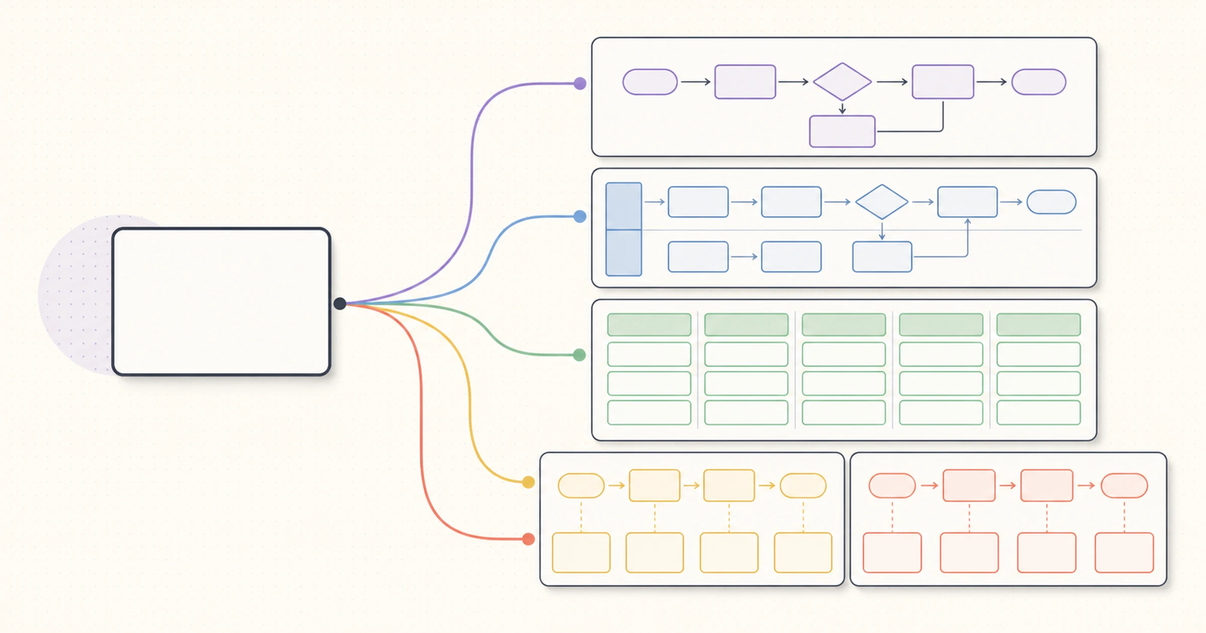
| BPMN model | How should a process and participant interaction be represented using standardized semantics? | Pools and lanes have defined roles | Formal specification | Events, gateways, messages, consistency, or model exchange require rigor |
A cross-functional flowchart is often another name for an informal swimlane diagram. A swimlane process map is a process map whose lanes emphasize responsibility. The label matters less than a shared legend—unless the team claims a formal standard such as BPMN.
If a basic flowchart is enough, an elaborate lane model adds maintenance cost. If a swimlane diagram hides participant-to-participant communication that must be precise, a BPMN collaboration may be more appropriate. For a simple tool-oriented starting point, see the online flowchart maker guide or the steps for creating a flowchart in Google Docs.

Common swimlane diagram mistakes
- Titles replace responsibility. Use the participant or system that actually acts.
- Detail levels are mixed. Keep one process level and link child flows.
- Decisions are unlabeled. Write the question and every outcome.
- Scope is unclear. State the trigger, completion condition, and exception ends.
- Connectors cross everywhere. Reorder lanes or extract a subprocess.
- Only the happy path exists. Add meaningful exceptions, owners, and routes.
- Policy is treated as reality. Mark steps as prescribed, observed, proposed, or confirmed.
- Layout implies evidence. Canvas distance is not time, capacity, or causation.
- No maintenance owner exists. Assign one owner and review date.
- Color carries all meaning. Combine it with labels, shapes, order, and a text companion.
Make the swimlane accessible
An accessible diagram is understandable beyond the original workshop. Give it a descriptive title and alt text. Preserve one reading direction. Use sufficient contrast and combine color with labels or shape. Make decision outcomes explicit and avoid hover-only explanations.
Keep the text table beside the visual. It provides a linear reading order, supports screen-reader access, and makes inputs, outputs, evidence, and exceptions searchable. Do not embed essential paragraphs as tiny image text. When sharing a large canvas, offer a focused export and a source where readers can zoom without losing context.
Organize the workflow in AFFiNE
Use an AFFiNE page to record the scope, lane definitions, step table, assumptions, evidence, and validation decisions. Use the Edgeless view to arrange the same working context spatially when the team needs to explore handoffs and exceptions. For a wider facilitation workflow, see project planning on a collaborative whiteboard.
Verify current AFFiNE behavior before publishing a team procedure. AFFiNE can organize documents, visual relationships, links, and collaborative review. It does not automatically discover a process, validate BPMN, simulate capacity, prove a root cause, or guarantee improvement.
Frequently asked questions
What is a swimlane diagram?
A swimlane diagram is a flowchart divided into lanes for participants, teams, roles, or systems. Activities sit in the responsible lane, and connectors show sequence and handoffs.
What is the purpose of a swimlane diagram?
Its purpose is to expose responsibility and handoffs. It can reveal unclear ownership, duplicated checks, rework, missing decisions, and exceptions, but cannot prove delay or causation without evidence.
What symbols are used in a swimlane diagram?
Informal diagrams use lanes, endpoints, activities, decisions, connectors, and evidence notes. Add a legend. Formal BPMN assigns defined semantics to its events, activities, gateways, flows, pools, and lanes.
How is a swimlane diagram different from a flowchart?
A flowchart emphasizes sequence. A swimlane diagram also groups activities by responsibility. Use lanes when cross-functional movement matters.
What is the difference between a pool and a lane in BPMN?
In BPMN, a pool represents a participant in a collaboration, while lanes sub-partition activities inside a process or participant. Sequence flow remains within a pool, and message flow represents communication between separate participants. Check the current OMG BPMN specification before claiming formal compliance.
Should swimlanes be horizontal or vertical?
Either can work. Match the reading flow, publishing format, and fewest crossed connectors; keep one orientation and provide a linear text companion.
How do you validate a swimlane diagram?
Walk a normal case and a meaningful exception from trigger to end with the people who perform the work. Confirm every owner, input, output, decision, branch, handoff, system, and evidence source. Record disagreements, assign a map owner, and set a review date.
Start with one real handoff
A useful swimlane diagram is not the one with the most symbols. It is the one a new reader can follow, the people doing the work recognize, and the process owner can maintain. Define a bounded trigger and end, map one observed path, make every handoff explicit, then validate an exception before polishing the canvas.
Last reviewed: August 15, 2026.
Recommended review: a process-improvement or business-analysis practitioner should verify the example, notation boundary, and accessibility before publication.